Alternating Current Electricity
Alternating current electricity (called AC) differs from DC electricity because both the voltage and the flow of current challenge both in magnitude and direction. If one were to plot the flow of current in an AC circuit as a function of time, the result would be like that shown below. The shape of this plot is usually called a sine wave. The amount of time that is required for the current to start from zero, increase to its maximum and decrease back to zero is the same as the time required for the current to decrease to its minimum and return to zero. The time required for the current to complete this cycle is defined as its frequency.
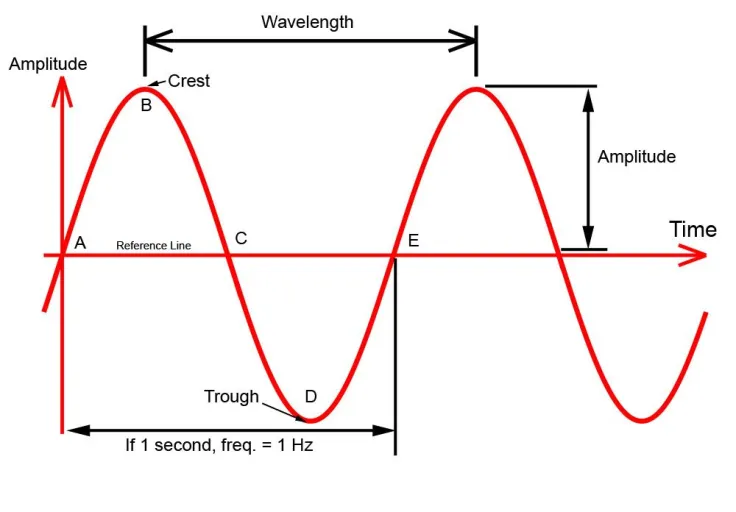
The more rapidly the current flow changes back and forth, the higher the frequency. Commonly, the frequency of AC power in the United States is 60 Hertz (hertz is commonly abbreviated as Hz and may be thought of as the number of cycles per second). There is nothing “magic” about 60 Hz and in fact in many parts of Europe and Asia, AC power is generated at 50 Hz.
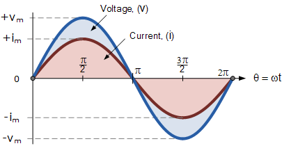
AC power has several characteristics that are fundementally different from DC power. These differences arise from the fact that when one plots the changing current and voltage in an AC circuit on the same graph, the two sine waves are usually not “in phase.”. The sine waves are out of phase when they do not reach their peaks and zeros at the same time. Below we can see an example in which the current lags the voltage
When dealing with AC circuits, the relationship discussed for DC circuits are similar but have important differences. For instance, when discussing Ohm’s Law, it is not sufficient to consider only resistance in determining how much AC current can flow through a conductor. Two other electrical parameters, capacitance and inductance also contribute to resistance to the flow of AC current. A new parameter called impedance is used to describe the total resistance from capacitance, inductance and resistance to the flow of AC current through a conductor. This allows us to write a new form of Ohm’s law for AC circuits:
E=I×Z
Where E = voltage in volts, I = current in amps, and Z = Impedance in ohms
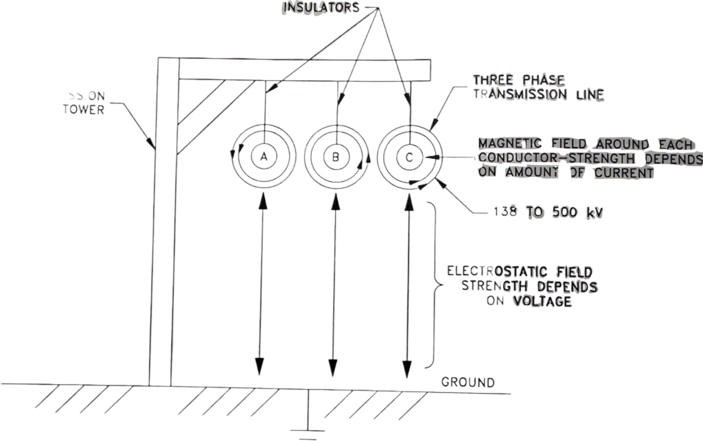
Capacitance exists whenever there is energy stored in an electrostatic field. An electrostatic field exists whenever there are two or more electrodes with different electrical polarity in close proximity to one another. Devices called capacitors consist of electrodes, usually in the form of metallic plates, that are placed close to one another with an insulating material between them. A voltage is then applied across the capacitor plates. Another common situation in electrical distribution systems where there is capacitance is in high voltage power transmission lines. The transmission lines operate at a very high voltage while the ground beneath is at essentially zero volts. An electrostatic field exists between the transmission lines and the ground. This electrostatic field represents stored energy.
Inductance exists whenever there is energy stored in a magnetic field. As discussed earlier in this section this occurs any time there is current flowing through a conductor. If the conductor is a coil, the strength of the magnetic field and thus the energy stored in that field is increased over that of a straight conductor. Most electrical devices, such as motors and transformers, found in power plants and other large process plants and factories, have coils of wire through which current flows and so these devices act as inductances.
Considering the high voltage power transmission lines, there is a magnetic field that surrounds the power cables because of the current that flows through them. Thus the high voltage transmission lines store energy in both magnetic and electrostatic fields and so have both capacitance and inductance.
For most electrical distribution systems, the transmission lines have much more inductance than capacitance, as long as they are heavily loaded and so they have large currents flowing through the lines.
If the power flow, and thus current flow, through a high voltage transmission line is very low, however, the inductance goes down while the capacitance remains essentially the same, given that the voltage does not change significantly. This demonstrates that some elements in an electrical system may change their capacitive/inductive nature, and thus impedance, depending upon circumstance such as load. While there are some exceptions, in most electrical distribution systems, the sum total of the loads in most electrical distribution systems are inductive in nature most of the time.
Impedance can change if the frequency of the AC current changes even if nothing in the circuit changes. The direction of the change depends upon makeup of the elements in the circuit and the frequency. If the circuit has mostly inductance and resistance with little capacitance (the type of circuit usually found at the generator output terminals), the impedance goes down as the frequency decreases, and up as the frequency increases. For a circuit with mostly resistance and capacitance, the impedance goes down as the frequency increases and up as the frequency decreases.
There are other changes that result in moving from DC power to AC. In the calculation of power, a parameter called the power factor must be considered. The power factor is a number between 1.0 and zero that is used in the power equation:
P = E × I × pf
Most AC electric motors have power factors that range between 0.8 and 0.9. If an electric motor were to have a power factor of 0.85, then only 85% of the power one would expect based upon the DC power equation would actually be seen in the motor (called the apparent power). Thus, for instance, if a motor operating at 100 volts were to draw 10 amps, the apparent power would be 1000 watts but the actual power would only be 850 watts.
A simple AC Generator
A simple AC generator can be built with a horseshoe magnet and a single coil of wire. Remember that relative motion between a conductor and magnetic field must be present to induce a voltage in a generator, this is sometimes referred to a cutting lines of magnetic flux.
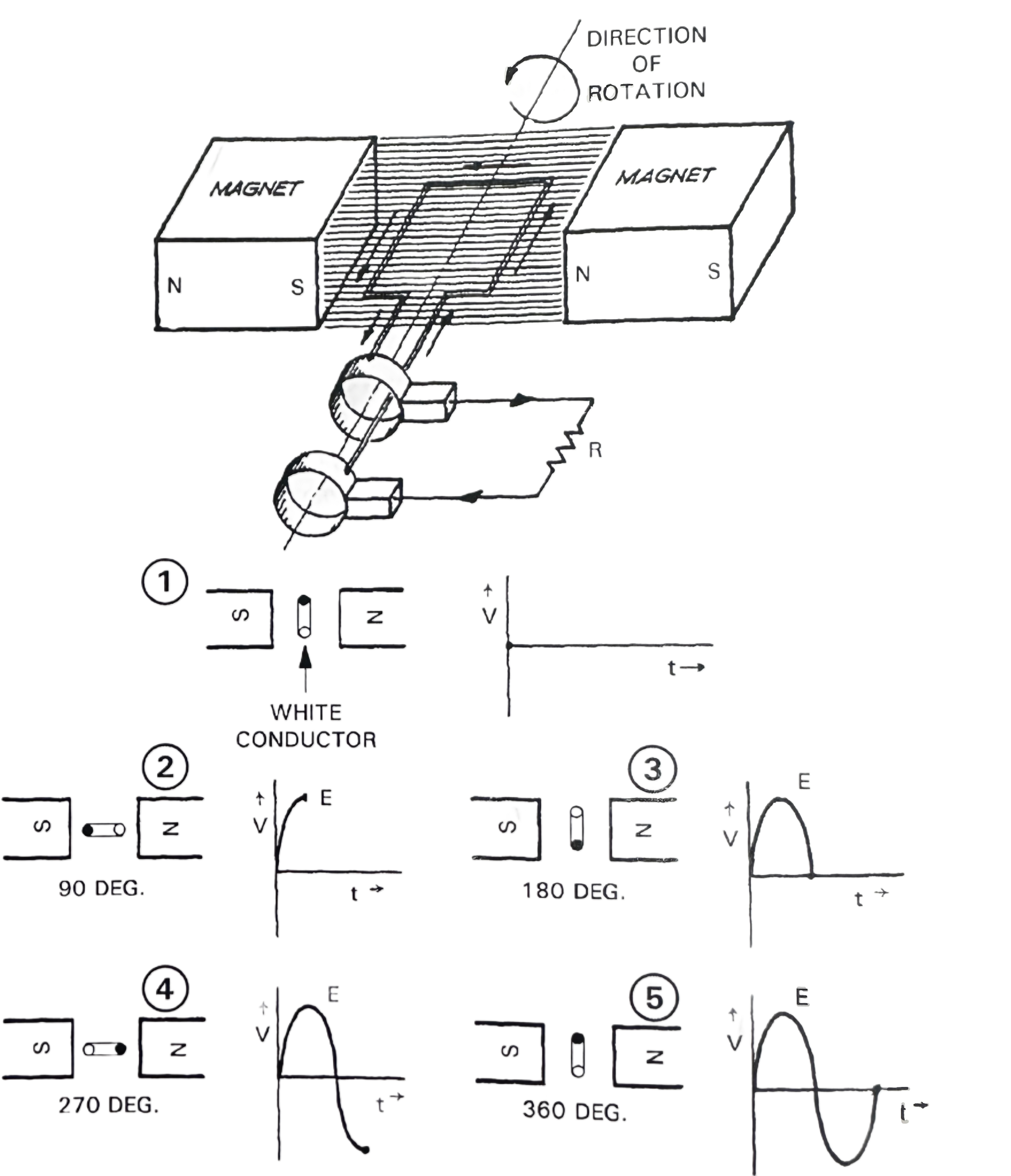
In the example above, the conductor is moving and a voltage is being induced in the conductor which causes current to flow. The white colored conductor passes near the north pole of the magnetic field and the voltage induced in the conductor increases in strength to a maximum value. As the white colored conductor reaches 180-degree position, the conductor is moving parallel to the magnetic field and so no voltage is induced in the conductor, because no lines of magnetic flux are being cut. When the white colored conductor passes next to the south pole (270 degree position), a maximum negative voltage is induced in the conductor. When the white colored conductor reaches the 360-degree position, a complete cycle has been completed, and no voltage is induced in the conductor because the conductor is again moving parallel to the magnetic field. In this case, one cycle of AC voltage is produced with each complete revolution of the conductor.
In this simple generator the rotating coil is called the armature and the stationary magnetic field created by the magnet is called simply the field. It is uncommon for generators to be built with this arrangement, however, because as discussed earlier, it is desirable to operate the generator at the highest possible voltage to minimize the production of heat (13,800 to 24,000 VAC). It is very difficult to operate a machine with voltages of more than about 1,000 volts at the slip rings. Accordingly, most large generators are built with a stationary armature and a rotating field. This arrangement makes it possible to connect the output of the armature directly to the load without slip rings.
Most large modern generators often have slip rings none the less, however these slip rings, usually called collector rings, are used for DC power to magnetize the generator rotor. The DC power is supplied at relatively low voltages (usually less than 600 VDC).
Three Phase Generators and Their Connection
Essentially all large generators generate three phase power. This is accomplished by installing three equally spaced sets of coils in the armature. In the three phase generator, one can plot the three sine waves of voltage. Each sine wave is displaced from the adjacent sine wave by 120 degrees. Each of the three armature coils in the generator has two ends. This means that the three phase generator has six terminals. These six terminals can be connected in two different ways. The most common connection is called the Wye connection, so called because the schematic of the connection resembles the letter “y”. In the wye connection, one end of each of three coils is connected to a common point called the neutral. The load(s) are connected between any two phases.
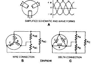
The second way in which a three phase generator can be connected is to connect each end of each coil to the adjacent coil. The result is called the delta connection because a schematic of the connection appears to be a triangle which is the Greek letter delta. The load(s) for the Delta connection are connected in parallel with the coils.
It is interesting to note that for a three phase generator connected in Wye, the voltage “seen” by the load is 1.73 times greater than the voltage in any individual coil. Thus, if the voltage induced in a coil is 1000 volts, the voltage seen by the load is 1730 volts. Since, as described earlier, higher voltages result in lower heat production and losses for a given amount of power delivered. This is one reason that most generators are connected in Wye.
Most Wye connected generators have the neutral connected to ground, usually through a transformer. This is a safety measure since it allows the system to be grounded. It also makes it possible to transmit power with only three conductors since no external neutral needs to be connected from the generator to the user.
There is another interesting property of Wye connections. If the current in each of the three phases are exactly the same, there is no flow of current through the common connection or neutral. If there is an imbalance of phase currents, however, there is a current in the neutral. As the imbalance in phase currents increase, the current in the neutral increases as well. This fact is used in providing protective relays for the generator that protect against the effects of unbalance phase currents.
The simple drawings above show all three phases. Electrical schematics for three phase systems are often drawn with a single line representing all three phases. This is done to simplify the drawing and make it easier to read. Such electrical drawings are called single line diagrams.
Induction Motors and Synchronous Machines
There are many similarities between motors and generators. A good understanding of the principles involved in the operation of the generator can be understood best by first examining the operation of the induction motor and then contrasting it with synchronous machines like the large AC generator.
Most people are aware that the rotor of most generators is magnetized by making it an electromagnet. Many people do not realize that there is a second magnetic field inside a generator in operation. This second magnetic field can be thought of as the “system field” because it is created by the flow of AC power in the three phases of the generator. This system field rotates at a speed that is dictated by the system frequency. If the system frequency is 60 Hz, the rotational speed is exactly 3600 rpm.
Three-phase, induction motors are very similar to generators with one major difference, they have no external source of excitation.. Most induction motors have a coil wound around the rotor that is continous and is not brought out through slip rings. Like generators, however, induction motors have a system field rotating at 3600 rpm inside.
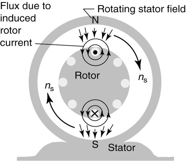
To understand how the induction motor works, consider the startup of an induction motor. At the instant that the breaker for the induction motor is closed, the rotor is at a standstill. Since the system field is rotating at 3600 rpm, the coil on the rotor “sees” a very rapidly changing magnetic field that induces a large voltage in the coild, that in turn causes current to flow and magnetize the rotor. As soon as the magnetic field is generated in the rotor, the system field “grabs it” and exerts a torque on the rotor that results in the rotor spinning in the same direction as the rotation of the system field.
The rotor accelerates to nearly the same speed as the system field but never reaches that speed. This is because if the rotor were tor turn at the same speed as the system field, the rotor coil would see no change in flux and so there would be no electromagnetism in the rotor. Instead, the rotor reaches a steady state speed that is slightly less than the system frequency. The difference in the system speed and the rotor speed is called the slip speed which is typically a few percent of the system field rotational speed.
If a load is imposed on the induction motor, it slows down, increasing the slip speed, thus increasing the rate of change of flux seen by the rotor and increasing the attractive force between the system field and the rotor. Thus, one characteristic of induction motors is that their speed varies with their load.
It is also possible to build another type of electric motor called a synchronous motor. The principal difference between the induction motor and the synchronous motor is the addition of an external source of DC current to the rotor, usually through slip rings. The outside source of DC power can be a battery, a DC generator driven by an induction motor or steam turbine, or a static system that converts AC power directly to DC.
Once this outside source of DC power for the synchronous motor rotor is supplied, the magnetic field in the rotor becomes independent of the slip speed. As a result, the rotor (assuming that it is a simple, two pole rotor) turns at exactly the same speed as the system field, called synchronous speed. In this condition, the motor is said to be synchronized to the electrical distribution system that is supplying power to the motor. The speed remains constant regardless of load as long as sufficient excitation power is supplied to keep the rotor “tied” to the system field.
The synchronous motor is an example of a synchronous machine. An important characteristic of a synchronous machine is the fact that it can either act as a motor to drive a load (like a pump or fan) or it can act as a generator driven by a device like a steam turbine, gas turbine, or a water wheel. The speed of a synchronous machine remains the same regardless of whether power is flowing into or out of the machine. In fact, it turns out that a synchronous generator can operate as a motor with no harm to the generator. This is called “motoring” the generator. Motoring is usually undesirable however, and so there is protective relaying provided in most plants to prevent the generator from motoring for more than about 5 to 20 seconds.
