Just an overview of H/X’s
Heat exchangers are plant components designed to transfer heat from one fluid to another. There are several different types of heat exchangers in the plant. The boiler, condenser, feedwater heaters, and lube oil coolers are some of the major heat exchangers. Even though some other equipment transfer heat, they are not called heat exchangers because they are not designed specifically to transfer heat.
There’s in general two categories that heat exchangers are grouped in for Utility plants
- Direct Contact Heat Exchangers
- Surface Heat Exchangers
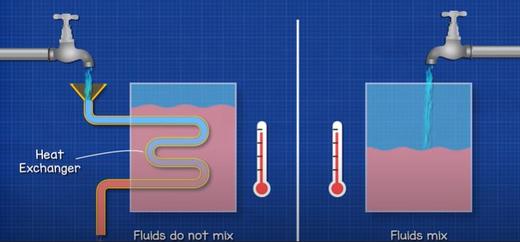
“Direct Contact” heaters are used in a number of power plant applications. In direct contact heat exchangers, the two fluids transferring heat come into contact and actually mix with each other. A cooling tower, where air mixes and cools the water, is a direct contact heat exchanger. In “Surface” type heat exchangers, the two fluids transferring heat are separated from each other by a surface, usually a tube wall. The convection process transfers heat from the warmer fluid to the tube surface. Then, the conduction process transfers heat through the tube wall and to the cooler fluid nearest the tube wall. Then, the convection process transfers heat to the remainder of the cooler fluid.
Direct Contact Heaters
Direct contact heaters transfer heat from one fluid to another through direct contact of the fluids. The two basic types of direct contact heat exchangers are the evaporative and complete mixing heat exchangers. In evaporative heat exchangers heat is transferred from a liquid gas, usually from water to air.
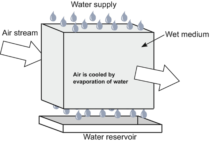
Air is brought into direct contact with the water to be cooled in an evaporative heat exchanger. Since the air is drier and cooler than the water, the air will absorb some of the water vapor. The energy carried away from the water cools the water and heats the air. The process is convective heat transfer because there is motion through the fluid. In a large power plant, this evaporation can be many thousands of liters per hour.
Open type heat exchangers transfer the heat from the warmer fluid to the cooler fluid by mixing the fluids together. The resulting mixture exits the heat exchanger as one fluid at one temperature. The heat transfer process is by convection, both fluids are usually the same substance in many cases it can be water and steam.
Surface Heat Exchangers
Heat exchangers that transfer heat from one fluid through a surface to another fluid at a lower temperature are called “Surface Heat Exchangers.” Most surface heat exchangers used in power plants are the shell and tube type. For example, feedwater heaters, condensers, and lube oil coolers are shell and tube surface heat exchangers.
Three types of shell and tube heat exchangers below are named for the direction of fluid flow:
- Counter Flow
- Parallel Flow
- Cross Flow
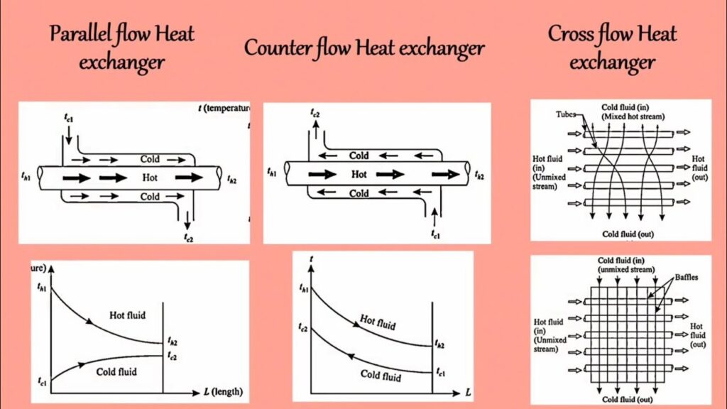
When two fluids travel in opposite directions on opposite sides of the tube wall are said to be in parallel flow. Finally, two fluids traveling at right angles to each other are said to be in cross flow. In all cases heat is transferred through the tube wall from the warmer fluid to the cooler fluid. In heat exchangers, the fluid temperatures change constantly as the fluids flow through the unit.
The amount of heat transferred through the tube wall is determined by the overall temperature difference. The overall temperature difference can be calculated from the largest and smallest temperature differences using higher level mathematics.
The rate of heat transfer in the heat exchanger is:

As can be seen from the equation, the larger the temperature difference, surface area, or heat transfer coefficient, the more heat transferered. If enough heat is transferred in a counter-flow heat exchanger, the existing temperature of the cold fluid may be higher than the exiting temperature of the hot fluid.
Counter-flow heat exchangers can transfer a relatively large amount of heat energy for their size, compared with the parallel-flow and cross-flow types. Most shell and tube heat exchangers have counter-flow type flow paths.
When the cold fluid enters the heat exchanger, the rate of heat transfer is relatively large because the temperature difference is large. As heat is transferred from the hot fluid to the cold fluid, their temperatures become closer to the same, and the delta T becomes small. Therefore, the rate of heat transfer decreases as the fluids travel through a parellel flow type heat exchanger.
Below is a cross flow heat exchanger. The more tubes used, the larger the surface area over which heat transfer can occur. Cross-flow heat exchangers are often used to condense or evaporate liquids. Turbine exhaust condensers are cross-flow heat exchangers
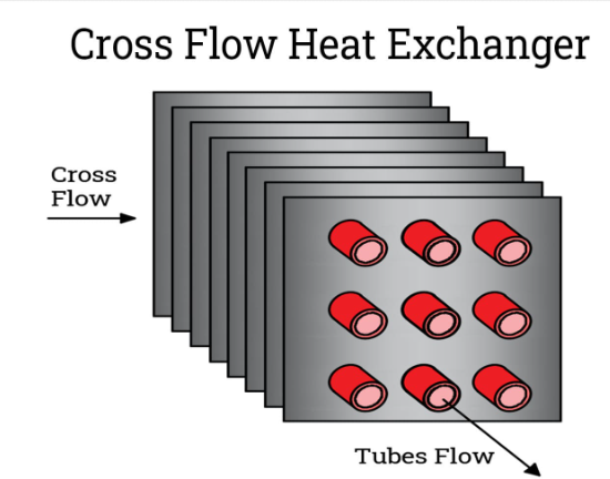
The turbine exhaust steam condenses as it flows across the condenser tubes. The latent heat of condensation given off by the condensing steam is transferred through the condenser tube walls and absorbed by the circulating water.
Steam condenses to water at the same temperature that water flashes to steam (The latent heat of condensation and evaporation involves a phase change, gas to liquid or liquid to gas, not a temperature change.) In ideal conditions, the temperature on the outside of the condenser tubes is constant.
Heat Exchanger Design
Heat transfer equipment is normally named for the function performed. Heaters are used to heat a fluid. Coolers are used to cool a fluid. The primary purpose for a condenser is to remove the latent heat of vaporization from steam or another fluid such as a refrigerant. Evaporators concentrate a water solution by evaporating the water into steam and then condense the steam to produce pure water.
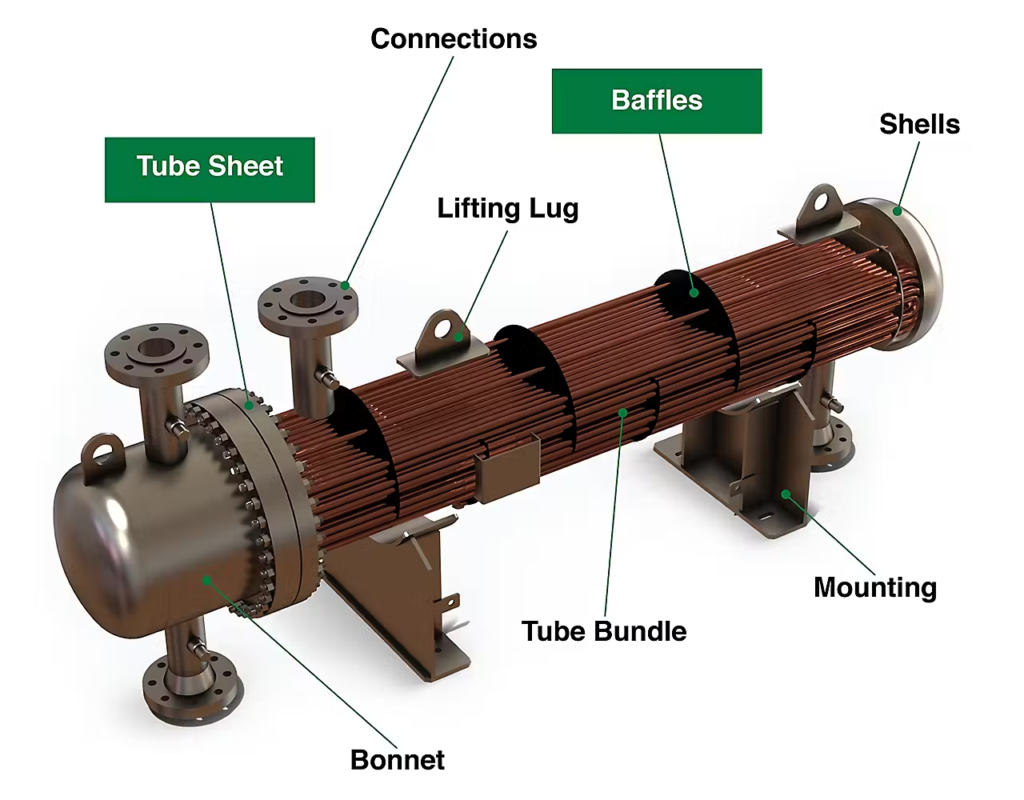
A typical heat exchanger contains a large number of tubes that increase the surface area for more effective heat transfer. When several tubes are used in a heat exchanger, they make up a “tube bundle”. Tubes are attached to a tube sheet. The tube sheet separates the shell side fluid from the tube side fluid. A simple counter-flow shell and tube heat exchanger is shown below
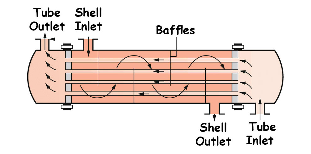
As the H/X warms up the tubes expand. One end of the tube bundle is designed to expand and contract with thermal expansion to prevent damage to the tubes. A common way to allow a tube bundle to expand and contract is to use a floating head, where one tube sheet is allowed to slide to absorb the expansion. Heater tubes can be arranged in several different ways including:
- Straight tube
- Coil tube
- Bowed Tube
- U-Tube
In straight tube type heat exchangers, the tubes are arranged in a bundle and enclosed by the shell. Straight tubes allow easy mechanical cleaning of tube interiors. Straight bundles can also be easily removed for replacement. Normally, heaters with straight tube bundles have one floating heat.
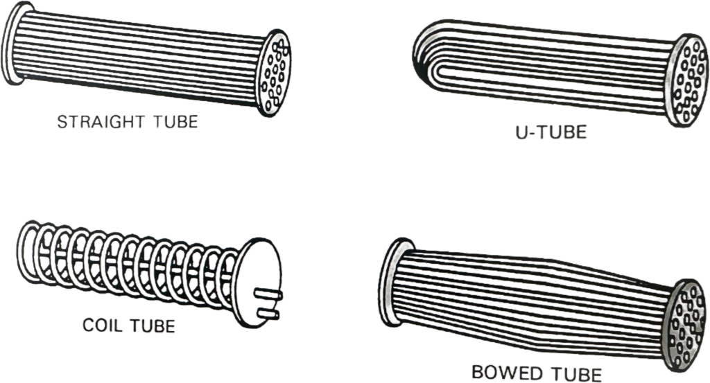
Coil tube type heat exchangers have one or more coils of tubing installed inside a shell. Since expansion is absorbed in the coiled tube like a spring, seals or gaskets are not needed between the floating head and the shell. Coil tube heat exchangers are therefore suited for high pressure applications. These heat exchangers are usually small and often used for sampling coolers for boiler water and steam.
Bowed tube type bundles can be solidly bolted to the shell at each end. The bow in the tubes allows for thermal expansion. An advantage of bowed tubes is as the tubes cool, any scale buildup on the inside or outside of the tubes crack off as the tubes bend.
In a U-Shaped tube h/x only one tube sheet is needed. The tube sheet is rigidly attached to the shell. The tubes are free to move back and forth within the shell when heated and cooled. Exceptionally long U-tubes are normally supported in the shell. A disadvantage of U-tube bundles is that it is difficult to mechanically clean the interior and exterior surfaces of the tubes. However, U-tube h/x are the most common heaters used to heat feed water in a power plant, mainly due to their enhanced efficiency.
H/X tube surfaces can be “Plain” or “Extended”. Plain surface tubes are smooth. Examples of plain surface H/X’s in the power plant are the condenser, feedwater heaters, and lube oil coolers. Some tube surfaces are extended with fins, rings, studs, grooves, or some other type of extension to increase the heat absorption efficiency. The main advantage of extended surfaces is the increase in surface area for heat transfer. Gas-to-liquid heat exchangers often use extended surface tubes, with the gas flowing through the finned side of the tube. Gases need a larger surface for heat transfer than fluids because they have lower convective heat transfer coefficients. Examples of extended surface heat exchangers are hydrogen coolers, economizers, and steam coil heaters.
The condenser is usually the largest shell and tube heat exchanger in the plant. It can have thousands of tubes carrying circulating water. The shell may be oriented horizontally or vertically, depending on the space available. Large units are designed to operate in a specific orientation, either vertically or horizontally.
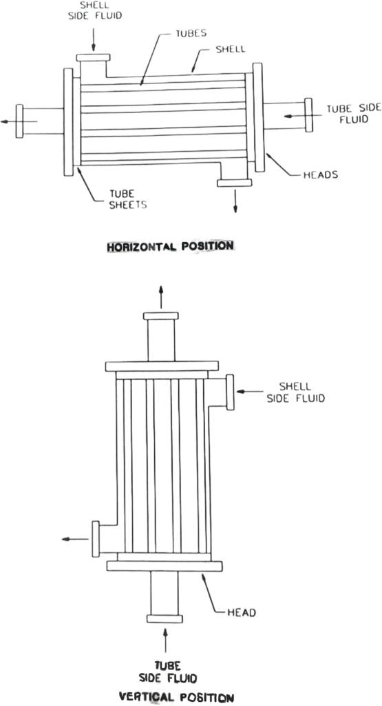
A shell and tube heat exchanger can be arranged with any number of tube or shell passes. Multiple passes allow the heat exchanger to be shorter with effectively the same tube length as a long single-pass heat exchanger design.
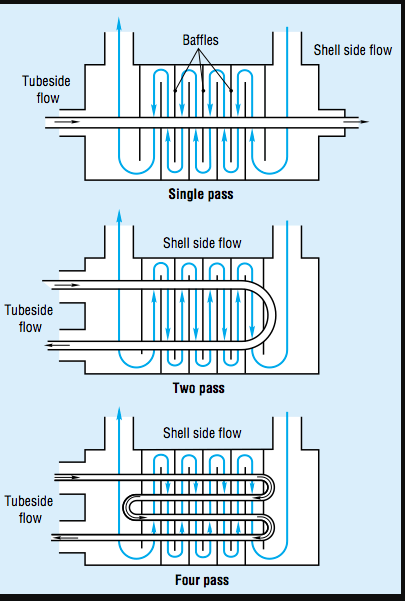
There’s simple single-ass tube single pass shell heat exchangers. There’s two pass tube single pass shell heat exchangers where the tube side fluid enters and exits through the same head. A division plate in the head divides the incoming and outgoing tube side fluid. U-tube heat exchangers (two-pass tube, single- pass shell) are normally designed this way. A two-pass tube, two pass-shell heat exchanger has a plate added to the shell to channel the shell side fluid through the heat exchanger twice. And there’s even four-pass tube, two-pass shell exchangers, where two plates in the head direct the tube side fluid back and forth through four passes in the shell.
Fluid flow through the shell will take the shortest route (path of least resistance) from the inlet to the outlet. This problem is solved by installing baffles to the shell interior. The baffles direct the fluid over the tubes in all parts of the heat exchanger.
BAffles cause the fluid to cross several times while still maintaining an overall counter-flow direction to the fluid in the tubes. This creates a heat exchanger flow path with a combination cross and counter-flow heat transfer.
The materials used in heat exchangers depend on service conditions, cost, and thermal conductivity. Cooling towers are usually built with concrete, wood, and plastic. Most other heat exchangers are made of metals with good heat transfer qualities and properties that are not easily damaged by the fluid flow.
The type, temperature, and pressure of the fluids passing through the heat exchanger determines the type of material. For corrosive fluids like water containing chlorides or salt, stainless steel or even titanium metal may be used because of corrosion resistance. Other metals used in heat exchangers include carbon steel, copper, brass, aluminum, admiralty, and montz.
It is common in shell and tube heat exchangers for the tubes to be of one material the shell of another. The shell can sometimes be made of a less costly metal like carbon steel, and the tubes of a more corrosion-resistant (and expensive) metal like stainless steel.
The flow of fluids wears away the tube metals. After long use, heat exchanger tubes may become too thin to be a reliable pressure barrier. In these cases, all the tubes may be removed and replaced with new ones. This is called retubing. The heat exchanger may be retubed with improved metal tubes for a longer life. Sometimes complete retubing is not feasible because of time constraints or not all the tubes need replacement. Sometimes, many good tubes are also replaced because they have to be removed to gain access to the bad or old tubes.
